Power Supply
240 V AC L,N,E
Preferably supplied from a local fused spur, fused at 3A
FlowK is fused internally with a 1A anti-surge 20mm fuse
Inputs
Pumps
A. Variable Speed Drives
Set S1, 1-8 to [OFF]
FlowK can monitor the speed of up to 4 pumps, 3 of which can be running at any one time, i.e. duty/1st assist/2nd assist/standby.
P1 – P4
4-20mA representing pump speed
Observe polarity
Input impedance 200 ohms
Unused inputs to be left unconnected
B. Fixed Speed Pumps
Set S1, 1-8 to [ON]
FlowK can monitor the state of up to 4 pumps, 3 of which can be running at any one time, i.e. duty/1st assist/2nd assist/standby.
P1 – P4
Connect to volt-free contacts
Contacts closed = pump on
Unused inputs to be left unconnected
Flow Meters
FlowK can monitor up to 2 flow meters.
F1 – F2
4-20mA representing flow rate in l/sec
Observe polarity
Input impedance 200 ohms
Unused inputs to be left unconnected
Digital Inputs
DI1
Not used in this application
Install link
DI2
Wet well high signal
Volt-free contacts, CLOSED = Level OK
OPEN = Well level high
Outputs
FlowK has 4 relay outputs for connection to an external device such as a telemetry outstation.
All outputs are single pole changeover volt-free contacts rated at 2A, 30VDC, resistive loads only.
RO1 – HIGH Alarm
RO2 – LOW Alarm
RO3 – SYSTEM Alarm – indicates a malfunction of the FlowK device
RO4 – “Well High – Low Flow” Alarm
For full explanation of the functions of the relay outputs please see later sections of this manual.
Battery back-up stystem
FlowK contains two levels of battery back-up.
System 1 provides power to maintain the real time clock for >6 months without mains power.
System 2 is a 9V PP3 battery and provides limited functionality during short, <20 minutes, power outages. The PP3 also provides a boost during periods of intense modem activity.
SD Card
FlowK records important data to an SD card every 30 seconds. In addition, every alarm issued by FlowK is recorded to the SD card together with all important parameters at the time of the alarm. The supplied 4Gb SD card will hold approximately 30 years of data.
Modem
FlowK contains a gprs modem with the following functions:
- An sms message will be sent to a designated number for every alarm issued by the FlowK unit. The sms is sent immediately on the alarm being issued.
- At 00.05 hrs the modem uploads all of the data recorded during the previous 24 hours to a website. A single .csv file contains all of the 30 second data recorded to the SD card in the previous 24 hours. In addition, a second .csv file contains details of any alarms issued in the 24 hour period. In the event of an upload failure repeated attempts will be made at hourly intervals till 05.05.
- The modem enables limited changes to be made remotely to the FlowK settings.
Front Panel Indication
The FlowK front panel has 6 LED indicator lamps to show the status of the unit.
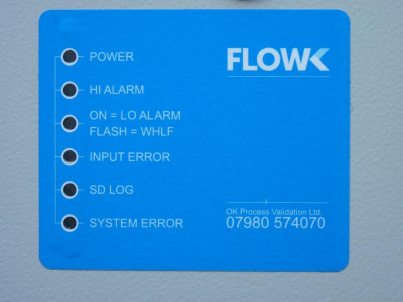
LED 1 – Power ON. Note that this LED will remain illuminated even if mains power is removed, provided that the rechargeable PP3 battery is capable of powering the FlowK.
LED 2 – High Alarm. FlowK has detected flow higher than expected. See later section of this manual for a fuller explanation.
LED 3 – If LED 3 is illuminated, FlowK has detected flow lower than expected. See later sections of this manual for a fuller explanation.
– If LED 3 is flashing, FlowK has detected a “well high” condition and the flow is lower than “consent”. See later sections of this manual for a fuller explanation.
LED 4 – Input Error. This indicates that an input has values outside the normal range.
LED 5 – SD Log. This LED illuminates when the FlowK is writing data to the SD card. This should flash briefly every 30 seconds.
LED 6 – System Error. This indicates that the FlowK processor has stopped. Please contact OK Process Validation Ltd for advice.